The Low Down On Time Delay Switches
The most important stuff first…
1 In all 2 wire applications where a neutral wire is not connected to the product, for the product to operate correctly, a minimum load of 35W must be connected to the LOAD side to ensure that a minimum current is available to power the microprocessor in the OFF state. If the minimum LOAD requirement is not achieved, then the product will not function correctly, if at all.
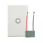
If a minimum connected LOAD of 35W cannot be achieved, then a load correction device must be wired in parallel to the connected LOAD. Connected Switchgear now offers a simple 2 wire load correction device (MLCD) that is compatible with all electronic switching devices, including our very own electronic time delay switch.
If the product is installed using the 3 wire method where a neutral wire is connected to the product, then the minimum load requirement is no longer necessary.
2 As an electronic relay switching device, it is imperative that the installer ensures that the combined inrush current load does not exceed the 10A rating of the relay. Failure to do so will reduce the life of the relay contacts and void warranty.
Here’s an example: let’s assume that the installed environment is switching 25 x 10W LED globes, meaning a combined total of 250W, the installer may assume that the connected load value falls way under the maximum rating current of the relay of 10A. However, what is not advertised on the LED globe packaging is the total power requirement (or inrush current) of the globe and in some instances can vary from almost 0 to as much as a factor in excess of 100. We have seen 7W LED globes with an inrush current as high as 50A! Imagine connecting 25 7W LED globes that have a total combined inrush current of 1250A!
What adds to the frustration is that manufacturers do not advertise this inrush current value on the product packaging. What we have experienced is that there is a link between cheaper alternative LED globes and higher inrush current values, so our recommendation is to stay away from the bottom end of the market when purchasing LED globes.
CSG is currently developing two new products that will eliminate this field problem related to electronic switching devices.
3 When the installation environment requires more than one switching point location, you cannot use 2 time delay switches to operate the one load. In this application, the installer must connect an AC type “momentary” press mechanism to the optional control switch terminal on the rear housing of the time delay switch.
Every time delay switch comes with an instruction sheet or can be downloaded from our website. We get that you are an experienced tradie and may have installed many electronic switching devices before, but each brand of product is unique. So don’t think you know it all and throw it out. Be sure to download and read the instructions carefully to see if this product is right for you.
Next, let’s discuss time settings…
Time out settings (ranging from 30 seconds to 259 minutes) are made by removing the front cover plate to access the micro switch toggles. There is no need to remove the switch plate from the wall. A total of 8 pre-set time out settings are available depending on the micro switch toggle set position, so follow the instructions to set the specific time out required. Type A and B programs allow a variety of installation and performance options:
Type A setting will commence programmed time out period each time the button is pressed. In the event that the button is pressed again prior to the pre-set time out, the program will recommence time out period again.
Type B setting will commence programmed time out period when the button has been pressed from the OFF position. If the programmed time out period has not expired when the button is pressed again, the programmed time out is cancelled and the switch is powered off.
Now, let’s talk specs…
Contact Status: Normally Open
Connection Type: 2 or 3 Wire (optional neutral wire)
Supply Voltage: 240V AC
Frequency: 50Hz
Max Current: 10amp
Over Temp Cut Out Current: 12amp
Max Load: 2500W (Incandescent) 2500VA (Fluorescent)
Minimum Load: 35W (when no neutral terminal)
Operating Temperature: 0 to 50°C
Cycle Timer Range: 30 seconds to 259 minutes
Factory Setting: 30 seconds, Type A Program


